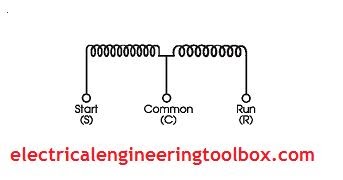

Chroma's low power AC source has sense leads to eliminate resistance and inductance in the leads from the AC source to the motor winding. Calculate the impedance of the winding using the formula below and the measured voltage and current from the AC source.

The following equations can then be used to calculate the inductance from the measured voltage and current. An AC signal from the source is applied and both the voltage and current is measured. For an AC motor the AC source in connected to each stator winding. For a DC motor the AC source is connected to the armature winding. The voltage should be low enough so as not to apply enough current to damage the motors windings.

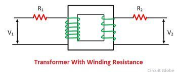
If you ever wondered how this can be accomplished, here you go.Ī low voltage AC signal can be applied to measure the inductance. The inductance of both AC and DC motors can be measured using a low voltage AC source. If a more accurate calculation is desired, the following example may be helpful. It is the responsibility of the customer to specify the required motor Hp, Torque and accelerating time for his application. For the iTIG III Model D the leads are the high voltage output leads so the micro Ohm winding resistance measurement can be part of an automatic sequence of motor tests including high voltage tests.The inductance or impedance of a motor can be a key parameter during the manufacture and servicing of both AC and DC motors. MOTOR FORMULAS AND CALCULATIONS: The formulas and calculations which appear below should be used for estimating purposes only. It eliminates the lead resistance and is typically more accurate.Īll winding resistance measurements done with Electrom Instruments motor testers are done with a four lead system. This type of resistance measurement will include the tester’s leads in the winding resistance test’s measurement. Resistance can be measured with two leads connected to a DUT. The difference in percent to the target resistance value is then calculated.Ī temperature correction factor can automatically be applied to correct the measurement to a standard temperature so results can be more accurately tracked over time with the winding analyzer. Hence we can conclude that a DC motor converts the input electrical power into. E b I a electrical equivalent of mechanical power developed in the armature. Using Ohm’s law the resistance is calculated in µΩ (micro Ohms) or mΩ (milli Ohms) by the winding analyzer.įor a 3-phase motor, 3 resistance measurements are normally done between the phases, and the balance or imbalance between the 3 measurements is calculated and displayed along with the measurement values.įor single coils and sometimes for motors, the resistances measured may be compared to a resistance value instead of having a balance calculated. The electrical power lost in the primary rotor and secondary stator winding resistance are also called copper losses. Multiplying both sides of the above equation by I a, we get, Where, VI a electrical input to the armature. Hence, increasing the rotor winding resistance leads to a higher starting torque. The black arrow, pointing left, indicates an increasing rotor winding resistance in the pointed direction. Winding resistance tests are a measurement of the applied DC voltage and current to the device under test -DUT. dependence of torque-speed characteristics on rotor resistance is shown in Figure 7. Some of these are the wire gauge issues, resistive connections, and blown or disconnected magnet wires in hand. immediately remove AC supply lines and connect DC lines across any two phase and apply 50 percent of the rated current of the IM to get the accurate DC. to get accurate value of DC resistance, firstly do block rotor test so winding of the motor get heated up at rated current. Winding resistance is an important measurement because other tests and measurements will not find some of the problems a resistance measurement will find. in case you want to calculate induction motor winding resistance.

The winding resistance test is used to find open windings, shorts to ground, wrong turn count, wrong wire gauge, resistive connections, round wires in hand that are not connected in a coil, some connection mistakes, the resistance balance between phases, and in some cases shorted turns.


 0 kommentar(er)
